Monday, January 25, 2016

Pi GPIO pins Control

Controlling Input and Output Pins:
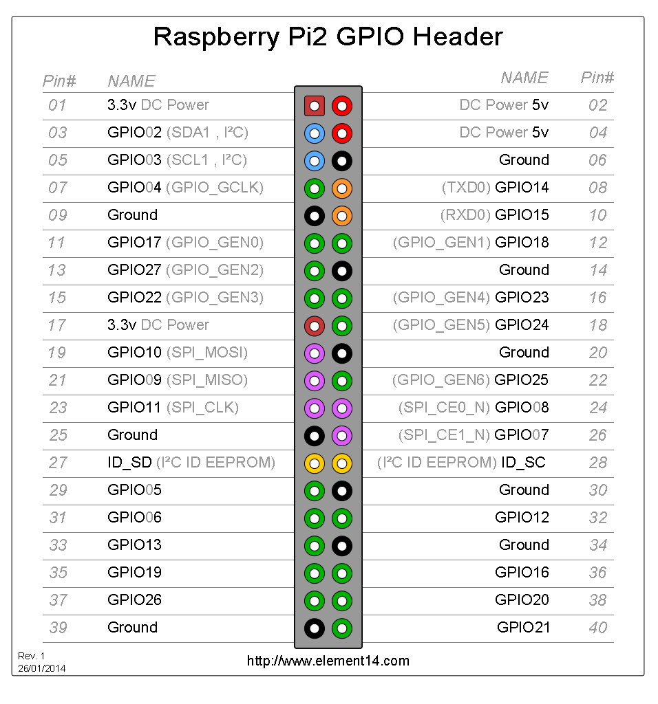


The Raspberry Pi2 is designed with a 40-pin connector that can be controlled by software.
The 40-pin header is made-up of many general purpose input and output(GPIO) pins.
Below is the complete pin diagram of Raspberry Pi2 GPIO Header.


 Lessons learnt form chapter:


·       Electronic circuits: Closed circuit, Open circuit, Short Circuit.
·       Current in a circuit, Voltage around the circuit, Resistance of the circuit.
·       Light emitting diode (LED)
·       Breadboard and its layout, connection of raspberry pi to breadboard.
·       GPIO Header:  pin numbers and their configuration.
·       GPIO pin as basic output.
·       GPIO pin as basic input.
·       Pull-up and Pull-down resistors.


 My Experiments:


1.       Using Pi as power supply to LED:

Things Needed:

·       R-Pi
·       40 pin GPIO Ribbon Cable with T-Shaped Breakout Board/ female to male wires
·       Power Supply
·       LED
·       Resistor (330 ohms)
·       Jumper wires

Process:

               First connected the GPIO header to T-Shaped Breakout Board using the 40 pin female to female GPIO Ribbon Cable. Next inserted the T-Shaped Breakout Board on the breadboard with the pins on either side of the center division on the breadboard. Instead of female to female to GPIO Ribbon Cable with T-Shaped Breakout Board, can also use female to male wires directly. Connected a wire from pin1 of the GPIO header with 3.3 V to anode (+ve terminal) of the LED. Other end of LED is connected to resistor. The other end of the resistor is connected to GND (any GND pin of GPIO header). The circuit connection is completed.
Switched on Power supply to Pi, LED turned ON.


2.       Controlling GPIO2 Pin as Basic Output:


Things Needed:

·       R-Pi
·       40 pin GPIO Ribbon Cable with T-Shaped Breakout Board/ female to male wires
·       Power Supply
·       LED
·       Resistor (330 ohms)
·       Jumper wires

Process:

                The pin3 or the GPIO2 pin of Pi can be used as the Input/Output.
The functionality of the pin is controlled by python program. Before that in order to test the functionality first modified the above circuit by simply connected the anode of LED to the GPIO2 pin instead of the 3.3V pin. Then switched on the power supply and executed the below python program from terminal. The LED is now blinking.

Program:


import RPi.GPIO
import time

RPi.GPIO.setmode(RPi.GPIO.BCM)
RPi.GPIO.setup(2,RPi.GPIO.OUT)

while True:
                RPi.GPIO.output(2, True) # RPi.GPIO.output(2, RPi.GPIO.HIGH)
                time.sleep(1)
                RPi.GPIO.output(2, False) #RPi.GPIO.output(2, RPi.GPIO.LOW)
                time.sleep(1)

Wrote the program, to make the LED glow for 1 second then stop. This is because, alternatively made the GPIO2 pin high and low. 

Done varies experiments by different series and parallel connection and also used different I/O pins for the experiments.

Experiment Results:

The I/O pins of Pi can be used as basic output source.
With different Combinations of the input like serial and parallel connection LED brightness varied due to different voltages in different connection.
In parallel connection all the LED glow with same brightness and vice versa in series due to varied voltages.


3.       Controlling GPIO2 Pin as Basic Input:


Things Needed:
·       R-Pi
·       40 pin GPIO Ribbon Cable with T-Shaped Breakout Board/ female to male wires
·       Power Supply
·       LED
·       Resistor (330 ohms)
·       Jumper wires
·       Momentary Push Button

Process:
               The pin3 or the GPIO2 pin of Pi can be used as the Input/Output.
The functionality of the pin is controlled by python program. Before that in order to test the functionality first need to construct the circuit as below. Connected the VCC point to pin1 for power supply and resistance from it and other end to GPIO2 pin. Then connected the Button between GPIO2 and GND.


Program:
import RPi.GPIO
import time

RPi.GPIO.setmode(RPi.GPIO.BCM)
RPi.GPIO.setup(2,RPi.GPIO.IN,pull_up_down=RPi.GPIO.PUD_UP)

while True:
  if RPi.GPIO.input(2) == RPi.GPIO.LOW:
              print("switch pressed.")
              break
RPi.GPIO.cleanup()

Wrote the program, to check the GPIO2 pin value. When switch pressed the GPIO2 pin gets low and release its high again. 


Experiment Results:


The I/O pins of Pi can be used as basic input source. Tested the experiment by using LED too.
In this case used the internal resistance of the pi too.


Internet of Things

Internet of Things - the name itself signifies that it's the communication of different objects for the information exchange. It is the network of physical objects like automobiles, buildings with other items embedded with electronics, software, sensors and the network connectivity that enables these objects to collect and exchange data. It has been labeled as "the next Industrial Revolution" because of the way it will change the way people live, work, and businesses interact with the world. Like we can automate the closing of blinds when the sun sets, automatic stock tracking in vending machines, monitor the health condition of people and send messages instantly if a person heart rate decreases, fire detection in the forests, temperature monitoring at home etc.. These all possible due to the Internet of Things. And, I will post here all my course work for 'CSC_9010 - Internet of Things' at Villanova University under the guidance of Professor Paul Schragger. 

The IoT kits I'm going to work in this course are:
1.Virlos Raspberry Pi 2 
2. Arduino ESP8266 kit
Apart from these, I will  use different sensors for my final project.

Week -1 :

My first experience working with Raspberry pi 2 Kit was wonderful. It contains so many different things in it. I took out each and everything and gone through the entire user manual I got along with the get to make from familiar with the things in the kit. Further going through the blog you will come across different experiments I have done with the Pi2 starting from the initial setup.

The Raspberry Pi2 Initial Setup

Introduction:

The Raspberry Pi2 is a small computer, a very small computer. It consists of mostly the same parts as a standard desktop computer or laptop. The Pi may be less powerful than Windows PC, but it is still impressive that it fits all of the parts of desktop computer on a board only which is slightly larger than a credit card.

Applications of Pi:

  • As a regular computer. Can install a variety of operating systems on the Pi.
  • Playing games, movies files, music on your TV.
  • Providing Network Services etc.,

Installation of Raspbian to the Pi:

Raspbian is the operating system(OS) designed for the Raspberry Pi. It is a Linux distribution that is based on Debian, another popular version of Linux.
Installation of Raspbian can be done either by New out of Box Software (NOOBS) tool that can be run on Pi and helps in the installation of OS or using a Disk Image.


Installation of Raspbian OS using NOOBS:

Things Required:

  • Raspberry Pi Device 
  • HDMI Display 
  • USB Keyboard and Mouse 
  • An SD card with NOOBS installed (SC card supplied with Pi already contains NOOBS else can download from https://www.raspberrypi.org/downloads/noobs/, extract and copy to SD card)

NOOBS installation on SD card:
For Windows, first format the SD card using the platform-specific instructions below:

i. Download the SD Association's Formatting Tool from https://www.sdcard.org/downloads/formatter_4/eula_windows/
ii. Install and run the Formatting Tool on your machine
iii. Set "FORMAT SIZE ADJUSTMENT" option to "ON" in the "Options" menu
iv. Check that the SD card you inserted matches the one selected by the Tool(same drive)
v. Click the "Format" button


Next download the NOOBS from https://www.raspberrypi.org/downloads/noobs/.

Copy the extracted files onto the SD card that you just formatted so that this file is in the root directory of the SD card. Please note that in some cases it may extract the files into a folder, if this is the case then please copy across the files from inside the folder rather than the folder itself.


OS installation:

Connect the Pi to the TV using the HDMI cable. Insert the USB connectors of keyboard and mouse to the PI in the available USB sockets. Now supply power to the device.

The Pi will start and load the NOOBS tool. The display shows a list of operating systems that you can install. For installing Raspbian select it as OS type and click install which is on the top left corner. Once the installation is complete, Pi restarts and Raspbian starts for the first time. Now the installation is done.


Raspbian OS


Also tried installing Windows IoT Core


Instead of connecting to monitor, keyboard and mouse every time we can connect to Laptop. For this to do we first need to connect to the internet.

Internet Connection:


Connection to Network using Ethernet:

With the direct connection to the network router to the Ethernet cable socket on Pi using the Ethernet cable we can connect to the network.

Wi-Fi Connection:

Insert the Wi-Fi adapter and click on the network monitor that shows you the available Wi-Fi connections. Double click on your Wi-Fi network and provide the password and connect to the network.
At this stage we are done with the internet connection the next step is to connect to the pi from a remote desktop.

Remote Desktop Connection to Pi within network:

Things Required:

  • A Software application on Pi to connect using Remote Desktop. 
  • Network Connection 
  • IP Address of Pi 
  • Windows Laptop 
In order to connect from my windows PC, the Windows already comes with an application called “Remote Desktop”. I can use this to connect to your Raspberry Pi and use the desktop environment from a Windows computer. But need a small software application on Pi.

To install software from the command line:

On the Application Launcher, click LXTerminal and type the below command and Press Enter

Command: sudo apt-get install xrdp
Press Y and then press Enter.

To find the IP address of Pi:

On the Application Launcher, click LXTerminal and type the below command and Press Enter
Command: ifconfig

The address needed is the “inet addr” looks like 192.168.0.66
If connected to the network using Ethernet cable, check in “etho” section.
If connected to the network using a wireless adaptor, check in “wlan” section.

To start Remote Desktop connection from Windows:

Go to run Command or press Windows logo key + R. Type mstc and press Enter.
In the Computer box, type IP address of Pi and press Enter.
Then login using the Pi credentials.
Now, I can access the Pi from the laptop using the Remote Desktop Connection.


If we moved to a new network and want to connect to network from pi we can do so with the ethernet cable. First need to share the network connection.

In windows,
– Network and Sharing Center -> Change adapter settings (on left) -> Right click on wifi-network -> Properties -> Sharing Tab -> Tick ‘Allow…

Now, check the IP address of the Ethernet from properties-> IPV4 -> IP address

Now, from the command prompt check the IP address under the ethernet IP interface


Transfer Files to and from Pi:

Through secure copy(SCP) I can transfer/copy files from and to the computer to Pi.
Raspbian already supports this. But a client is required on the computer to do this.
Install WinSCP, a very popular application on Windows for transferring files. (can download from https://winscp.net)

Provide the File protocol as SCP, Host name as the IP Address of Pi and the username and password of the Pi to establish a connection to Pi.


Secure Remote Shell access to Pi using PuTTY

PuTTY is an SSH and telnet client, open source software and very versatile tool for remote access to another computer. You can download PuTTY here.
Using IP Address of Pi, username and password of the Pi can establish a connection to Pi.