Friday, May 6, 2016

Final Notes

It's going to be my last notes for this course and to Professor Paul Schragger too :)

From the bottom of my heart, I would like to thank two persons. One, Professor Paul Schragger, for building a perfect experience of a complete self-learned practical curriculum to 'Internet Of Things' course and made me think, research, exhibit and expose my hidden strengths to the world out there with this blog writing. Two, my friend, Prashanth who helped me right from the selection of this course till the end of the final project and its great experience working with him.

It's like I started this course 'Internet Of Things' just a few days ago. But to reality, it completed Century of days by now. Finally, Hurray! I have successfully completed my Course work after a great effort leaving behind with mixed feeling. This feeling right now I have is unexpressed. At this late hour of the night, I just felt like putting my feelings towards IoT on this blog. It's immaterial for me the grades but the more important is I had a complete set of varied experience in this course which helped me to increase my overall personality both at technical and management skills that need to be present in a person to fight with the world out there.

I would like to recall all the things starting from the selection of course till the end.

It's the start of the second half of my first semester, I need to register to the courses for Spring 2016. I just checked all the available courses and this Course 'Internet Of Things' catches my eye as it included some electronic stuff. I love Electronics and fun playing with IC's, Resistors, Diodes, Circuits. Missed them. It's almost 3 years I even thought of those.
As it's my first time to hear about a course like this, gone through some basic research, collected information from friends regarding the course structure and professor. I would like to thanks Prashanth for encouraging me to take the subject. Initially, I hesitate to take as its hard to balance 3 tough courses. But I took a step and decided I should face it and the battle started with the course registration :)

Then comes the first day of the class. Don't even  know what's will happen in this course. But I was full of excitement that I am going to play with the circuits again :) . The professor named Paul Schragger, really a cool person gave a perfect kickstart of the IoT. It's excited to hear about the kits we are going to use in the coursework. One the Raspberry Pi, and the other Arduino NodeMCU with ESP8266. And the rest of the story you can figure out from my Blog.

This course was really awesome. It's not something the same boring examination patterned course. It's something different, more practical, more self-learning with the Prof. guidance. There are hundreds of things I have learned in this course and its hard to point out all.

I have never thought I would write a blog, never think of my strength in self-learning, research, or in documentation and more. This course helped me in realizing my strengths and weakness, helped me to shape myself both technical and management skills.

Apart from the course work,

1.Attended few sessions on Arduino conducted by Engineering department at Villanova.

2.Participated in Arduino Hackthon dated 4/1,  where we build a project, inspired from an experiment conducted in china. It's about the automatic control of the car which can prevent the car accidents. In this hackathon, we formed a group of 5 persons - me, Prashanth, Sandeep, Jorge, Charan and worked with the Arduino UNO. We built a working Rover which worked based on the control of the accelerometer and predicted the obstacles using the ultrasonic sensor. Also, worked on the MQTT communications of the commands to operate the rover. Plan of the Hackathon:
https://drive.google.com/drive/folders/0B-7OVLV2uzmLMVlnbmlpaWFyZlU
We divided the project into 3 modules, me and charan worked on Rover operation from Arduino:  https://www.sparkfun.com/datasheets/Robotics/Rover%205%20Introduction.pdf 
and then controlling the movement based on the Ultrasonic sensor.


3.Volunteered for the Arduino workshop dated 4/23, but this time playing the role of Teaching Assistant for the 23 Indian students who had attended the Arduino workshop conducted by the Villanova Engineering department. It's really a wonderful experience of playing the role of teacher. In this, I helped the students to understand the Arduino and showed the example programs like LED blink, servo motor operation, LCD display of the Arduino SparkFun kit:  https://www.sparkfun.com/products/12060

And here comes the final Phase of the Course, the Poster Presentation of the final projects. It's really great to see different ideas. Here is the last day Picture captured for memories :)


Finally, the overall experience with IoT was ExtraOrdinary. Signing off - Jyothi.

Wednesday, May 4, 2016

Complete Final Project Report- Smart Blinds

Smart Blinds - A Home Automation Project

Here comes the final documentation of my IoT Project, 'Smart Blinds' - a home automation project.

Introduction:

Internet of Things has been labeled as “the next Industrial Revolution” because of the way it changes the way people live, work, and businesses interact with the world. With the advancement in Technology, we can build our own secure and safe environment. This project ‘Smart Blinds’ that comes with the inspiration of the concept of ‘Green House’ which helps the plants to have a safe environment.


Abstract:
                 The project is about 'Smart Blinds'. The key point here is the opening and closing of the blinds made automatic and which depends on the intensity of the outside light. Also, can analyse the duration of opening and closing of blinds.In this project, I have built my own Home Automation Project for the safety of kids and pets at home when we are away from home. For this, I chose to automate the blinds operation based on the time of the day, temperature and intensity of light.

1.Project Report:

For my project 'Smart Blinds' which is like any other IoT project, I would like to provide a complete detail of the project with explaining all the specifications starting from the high-level overview which gives a picture of what's the project is all about and then down to low-level overview which gives all the minute details of the project so that anyone who will come across the post can do the project all on their own from the data and references I'm going to share about this project.

HighLevel Project Flow Representation


The above diagram shows a High-level idea of the project which is generic to all the 3 modules I have done in this project. Here, the user can manually control the blinds based on the temperature displayed on the Blynk application and then sends the message to the control Signal Processor, in my application Arduino acts as controller which sends signals to the servo motor to rotate the blinds either to open or close them based on the instructions it received and then the position of the blinds is again passed back to the control circuitry for future reference. This is a complete high-level design of the basic functionality in my project.

Project Requirements:

Hardware:

  1. Arduino esp8266
  2. Raspberry Pi 2
  3. BreadBoard
  4. Jumper wired
  5. Photo Resistor
  6. DHT11 sensor
  7. Servo motor
Software:
  1. Blynk app( auth token)
  2. Arduino IDE 
  3. Mosquitto installed in Pi
  4. Mosquitto configuration 
  5. NOde-Red
  6. External URL to connect to Wearther API
  7. Python working on platform 
Arduino Libraries:
  • SPI.h
  • BlynkSimpleEsp8266.h
  • Servo.h
  • ESP8266WiFi.h
  • PubSubClient.h
  • DHT.h
Python Libraries:
All code of my project will be available at this link:

IoT design methodology:

The complete design methodology is defined in a total of eight Specifications.
  1. Purpose and Requirements Specification
  2. Process Specification
  3. Domain Model Specification
  4. IoT Level Specification
Please follow the below link for these specifications of the project:
http://myiotblog.blogspot.com/2016/04/fundemental-parts-of-project.html

       5. Service Specification
       6. Functional View Specification
       7. Operational View Specification
       8. Device and Component Integration

Please follow the below link for these specifications of the project:
http://myiotblog.blogspot.com/2016/04/project-report.html

NOTE : Updated the links with more data than the one previously submitted as part of Assignments.

Architecture:

Blynk Service Integration:
Blynk Service

In this service operation, the user controls the operation of blinds using the Blynk App. Based on the commands from the Blynk application the NodeMCU controls the direction,speed and rotation of the servo motor which will either open or close the blinds. Once done, then this change in the blinds position is recorded and published to the topic 'BlindsPosition' through MQTT protocol to the MQTT server where the Pi acts as the MQTT broker. Simultaneously, a python program is running on Pi which subscribes to the 'BlindsPosition' topic and continuously checks for messages. If any message published to the topic it subscribes and streamed the data to the 'InitialState' Cloud Storage.
There in dashboards are created to constantly monitor the blinds position.


 Weather API Service Integration:
Weather API Service 

In this service operation, the controls of the operation of blinds made automatic which was based on the external climatic conditions. It's based on two factors. one the time of the day and other the temperature. The use case diagram for this as below.

First checks whether its day or night and then checks if the temperature is greater than the threshold.
Based on these conditions the operation of blinds made automatic. The external data is extracted from the open weather API which is secured as it required the authentication key. A python program is coded which is running on Raspberry Pi extracts data from weather API for every 1 minute. It streamed the data to the 'InitialState' Cloud Storage. Also, continuously checks the conditions and if the temperature exceeds the threshold then published to the topic the command 'close' to the topic through MQTT protocol to the MQTT server where the Pi acts as the MQTT broker. Simultaneously, a program is running on NodeMCU which subscribes to the topic and continuously checks for messages. Based on the message it sends the control signals to the motor and then publishes to topic 'BlindsPosition' through MQTT protocol the position of blinds.
There are dashboards also created to constantly monitor the external conditions.


External Climate Parameters Storage Data

2. Project Poster:


Smart Blinds - Final Poster

Results:

Output Results in the InitialState Streaming DashBoard for all the information

This dashboard above will show the line graph details of each of the measurements stored in the cloud. Also, it adds new tiles with the information of the last value of the blind(like 'Open' or 'Close') , Histogram results of blinds position and lastly the pie chart results of the blinds position.
Line Graphs for all the measurements saved in the cloud


Blinds Position data Saved in the cloud and can be extracted as CSV file format

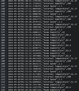
External and Internal Temperature, Humidity readings stored in cloud


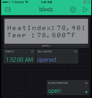
The above diagram depicts the UI in the BLYNK app from which the user is able to control the blinds operation. It has new features like a big closet. A User can even set the timer based on which the particular operation is performed. The user will have an option to view the current position, temperature and heatsink of device.

3. Demonstration:


4.Link to Software:

Blynk Software: It is used to interact and communicate with the Arduino to perform control actions so that user can remotely operate the blinds. It provides an interface as a mobile application where the user can give the inputs and can provide commands for the actions to be done. This one is secure as it provides a secure Auth Key for each and every project we created and with this access key only we can communicate securely.
1. We can track the position of the blinds using the display widget- 'Labeled Value'
2. Also, can continuously view the room temperature and the heat sink values which are displayed on the 'LCD display'.
3. Used the 'Menu' Widget to select the actions to either open or close of the blinds.
4. Provided the user with the option to preset the control of blinds at a particular time using the 'Timer' widget.


  1. Blynk Docs : http://docs.blynk.cc/
  2. Blynk Start Guide : http://docs.blynk.cc/#getting-started-getting-started-with-the-blynk-app
  3. Blynk Hardware Setup: http://docs.blynk.cc/#hardware-set-ups
  4. Labeled Value Display: http://docs.blynk.cc/#widgets-displays-labeled-value
  5. LCD Display Widget: http://docs.blynk.cc/#widgets-displays-lcd
  6. Menu Widget: http://docs.blynk.cc/#widgets-other-menu
  7. Timer Widget: http://docs.blynk.cc/#widgets-controllers-timer
Initial State:
http://blog.initialstate.com/category/arduino-2/


Raspberry Pi2:

NodeRed:


Arduino:

ServoMotor:

DHT11 Sensor:

Weather API:

5. Project Sites used in creating the project:
http://www.instructables.com/id/Arduino-controlled-automated-blinds-with-Web-UI/
https://www.hackster.io/cyborg-gibson-11/automated-blinds-by-cortana-7bfaff

6. Future Work and Project Enhancements:
  1. I would like to extend this further by providing SMS or EMAIL notification to the user which would be more helpful for continuous update and notification.
  2. I would like to further extend this work to the predict persons wish of blinds position based on the various factors (temperature, time of day).  
  3. Need to apply linear regression, decision tree using R programming for the predictions.
  4. Also, I would like to the monitor and analyze the health of the crops based on the different climate conditions like the wind, humidity, temperature and varied parameters which affect the plants growth.
  5. I would like to further extend it by handling all the blinds in the home by Integration.
  6. Monitoring the health of plants based on different climate conditions.

Thursday, April 28, 2016

Parts of Project Report

Smart Blinds- A Home Automation Project - Specifications-II

In my previous post, https://myiotblog.blogspot.com/2016/04/fundemental-parts-of-project.html
I have discussed the first four specifications of my 'Smart Blinds' IoT project.
In this post, I would like to discuss the remaining specifications of my IoT project.

5.Service Specification:

The fifth step in the IoT design methodology is to define the service specifications. Service Specifications define the services in the IoT system, service type, it's input/output, endpoint,schedules, preconditions and finally service effects.

There are two services in my project:
1.The Blynk service, which is used for change of modes of the blinds between open and close
2. A weather API service, for getting information about the temperature, luminosity etc., based on which the automation of the blinds controlled.

Blynk Service:

 In this service, the Blynk Application installed on the mobile phone from which the user is able to control the blinds operation. It is used to interact and communicate with the Arduino to perform control actions so that user can remotely operate the blinds. It provides an interface as a mobile application where the user can give the inputs and can provide commands for the actions to be done. This one is secure as it provides a secure Auth Key for each and every project we created and with this access key only we can communicate securely.

1. We can track the position of the blinds using the display widget- 'Labeled Value'
2. Also, can continuously view the room temperature and the heat sink values which are displayed on the 'LCD display'.
3. Used the 'Menu' Widget to select the actions to either open or close of the blinds.
4. Provided the user with the option to preset the control of blinds at a particular time using the 'Timer' widget.

The below diagram is the pictographic representation of the Blynk Service:


Weather API service:

 In this service, from the openweather API we can get information about the wind, humidity, and the temperature at our place using the python programming from Raspberry pi.
Based on which the operation of the blinds is automated. If the temperature is beyond the threshold then the blinds will be closed or else opened.

The below diagram is the pictographic representation of the Weather API Service:


Functional View Specification:

Goals:
1. To remotely access the control of blinds when we are away from home.
2. To automate the position of blinds based on the external climatic factors
3. To automate the position of blinds based on the internal room conditions.

Targeted Area:
Home and work area where it's needed to control the process remotely and automate the process to avoid any sort of risk to the kids, pets, and plants.

Modules:

The overall project is divided into three modules:
1. Remote control of the blinds by the user on his wish.
2. Automatic control of the blinds based on the information of the external climate from the openweather API.
3. Automatic control of the blinds based on the room temperature extracted from DHT11 sensor.


Device: The devices that are used for this project include the raspberry pi2, NodeMCU with ESP8266, Rotational servo motor, a Photo Resistor, DHT11 sensor.

Communication: The communications used in this project include the serial communication, restful web services, MQTT communication to transfer information about the blinds position to Raspberry pi where this streams data to the InitialState cloud server through the HTTP communication which is secured with the Authentication keys. Also used the HTTP protocol for extracting information from the open weather API.

Services: The different services in this project are the monitor, control services which are explained in the above  Service Specification section.

Management: The different managemental things include the installations, configuration of all the different software's that are needed which includes the BLYNK app, the blynk libraries that are needed for the communication to and from NodeMCU. The different python packages to communicate with the weather API and InitialState Cloud server.

Security: The security for the project is minimal as it operates under the secured home network, but still should have the basic user authentication for the BLYNK application, access to the OpenWeather API, and the InitialState Cloud server. All these require the authentication key in order to have access to them in my project which results in a secured environment.

Application: In my project, the application deployed locally on the NodeMCU, python programs on Raspberry Pi2 device and can be accessible remotely from BLYNK app and also can set timers to control the blinds.


Operational View Specification:

From this specification, we can have a clear view of project how it is realized based on various factors like the service hosting, storage, devices etc.,

Services:


  1. Blynk Service: Service used to control the blinds position from Blynk, a Mobile application
  2. Weather API service: Service which is used to extract the data (temperature, humidity, wind speed) from Open Weather API based on which the blinds position is automated.


Storage: All the data is stored in the InitialState cloud and there only dashboards are created to analyze the different factors which are extracted from weather API and data valuesfrom the sensors.

Devices: 

  1.  Raspberry pi2
  2.  NodeMCU with ESP8266
  3.  Rotational servo motor
  4.  Photo Resistor
  5.  DHT11 sensor


Application:


  1. Mobile Application - Blynk app
  2. Web API - OpenWeather API
  3. Web Dashboard - InitialState
  4. MQTT Server - Mosquiito Interface 


Communications Protocols:


  1. Link Layer:  Wireless LAN(802.11)
  2. Network Layer: IPv4 
  3. Transport: TCP
  4. Application: HTTP, HTTPS,MQTT


Security: 

Authentication and Access keys for:

  1. BLYNK app
  2. InitialState Dashboards
  3. OpenWeather API.

Management:


  1. Mobile Application Management : Blynk App
  2. Web Application Management : Initial State Dashboard
  3. Device Management: Raspberry Pi2, NodeMCU with ESP8266, Servo motor
  4. Server Management: MQTT server, Mosquitto for MQTT UI.
  5. DataBase Management: Initial State Cloud
Device and Component Integration:

Blynk Integration:
Blynk Basic operation

Rotational Servo Motor:

Rotational Servo Motor

DHT11 Sensor
DHT11 sensor connection with the raspberrypi2 


Blynk Service Integration:


In this service operation, the user controls the operation of blinds using the Blynk App. Based on the commands from the Blynk application the NodeMCU controls the direction,speed and rotation of the servo motor which will either open or close the blinds. Once done, then this change in the blinds position is recorded and published to the topic 'BlindsPosition' through MQTT protocol to the MQTT server where the Pi acts as the MQTT broker. Simultaneously, a python program is running on Pi which subscribes to the 'BlindsPosition' topic and continuously checks for messages. If any message published to the topic it subscribes and streamed the data to the 'InitialState' Cloud Storage.
There in dashboards are created to constantly monitor the blinds position.

Blinds Dashboard
Blinds Positon Data


Weather API Service Integration: 


In this service operation, the controls of the operation of blinds made automatic which was based on the external climatic conditions. It's based on two factors. one the time of the day and other the temperature. The use case diagram for this as below.

First checks whether its day or night and then checks if the temperature is greater than the threshold.
Based on these conditions the operation of blinds made automatic. The external data is extracted from the open weather API which is secured as it required the authentication key. A python program is coded which is running on Raspberry Pi extracts data from weather API for every 1 minute. It streamed the data to the 'InitialState' Cloud Storage. Also, continuously checks the conditions and if the temperature exceeds the threshold then published to the topic the command 'close' to the topic through MQTT protocol to the MQTT server where the Pi acts as the MQTT broker. Simultaneously, a program is running on NodeMCU which subscribes to the topic and continuously checks for messages. Based on the message it sends the control signals to the motor and then publishes to topic 'BlindsPosition' through MQTT protocol the position of blinds.
There are dashboards also created to constantly monitor the external conditions.
External Climatic Conditions Dashboard

External Conditions Data 


This Concludes the Specifications of my project. In my next post I would report a complete report of my project which also includes my further enhancements and anticipation of this project extension to the 'Green House'.

Code:
My entire project code is present at this link:
https://github.com/jyothi-lanka/IoT/tree/master/SmartBlindsProject


References:

TextBook: 

  •  Internet of Things: A Hands-On Approach By Arshdeep Bahga, Vijay Madisetti
  • Enabling Things to Talk- Designing IoT solutions with the IoT Architectural Reference Model Editors: Alessandro Bassi, Martin Bauer, Martin Fiedler, Thorsten Kramp, Rob van Kranenburg, Sebastian Lange, Stefan Meissner
Links:

Fundemental parts of project

Smart Blinds - A Home Automation Project


Here comes the final phase of my course. The final project which comes with the inspiration of the concept of 'Green House' which helps the plants to have a safe environment. Likewise, I would like to build my own Home Automation Project for the safety of the kids and pets at home when we are away from home. For this, I chose to automate the blind operations based on various factors like the time of the day, temperature and intensity of the light.


1.Purpose and Requirements Specification

Purpose: A home automation project for automatic controlling the operation of blinds based on the intensity of light, temperature, and time of the day. This can be based on the information from the weather API. Also, provides an option for the user to control the operation of blinds from his phone and can set the timer for the same.

Behaviour: The information about the light intensity, temperature, and time of day is collected from the weather API based on which the operation of the blinds is controlled. Later, the data about the blinds position is tracked, stored in local and cloud database and can be used for further analysis.

System Management Requirement: The system should provide remote control functionality to operate the blinds between open and close modes or should provide timer functionality to automate the process.

Data Analysis Requirement: The system should report data to the cloud database where the data will be analysed.

Application Deployment Requirement: The application should be deployed locally on the device, but can be accessible remotely or set timers to control the blinds.

Security Requirement: The security requirements for the project are minimal as it operates under the secured home network, but still should have some basic user authentication.


2.Process Specification:

The automation system can be performed in three different ways.

1. Using mobile application for remote control of blinds and can even specify the time frame to automate the control.


2. Using the temperature sensor reading at home and make the process automate by closing the blinds if the temperature is beyond the specified temperature threshold.


3. Based on the information about light intensity, temperature, and time of the day from the weather API can automate the blind control.


3. Domain Model Specification:

Physical Entity: The physical entity of my project is the blinds, which is my focus object that is controlled based on various factors like the time of the day, temperature, light intensity.

Virtual Entity:  The virtual entity of my project includes the various parameters I'm tracking for the control of the blinds. They are the time of the day, temperature, light intensity.

Device: The devices being used in my project are Raspberry pi 2, Arduino esp2866, servo motor, DHT11 sensor.

Resource: Raspberry pi 2, NODE-RED, mosquitto MQTT server on the device, Arduino IDE on the laptop.

Service: The service in my application includes the blynk cloud service, which is used for change of modes of the blinds between open and close and a weather API for getting information about the temperature, luminosity etc., based on which the automation of the blinds controlled.


IoT Level Specification:


My project was based on the Iot Level-2 with the following details.

Single device/node
Sensing or actuation
Remote/cloud datastore
Local analysis
Control via Rest
Central/cloud rest services for
Monitoring
Control

IoT Level -2


Sunday, March 20, 2016

Project Proposal Abstract

IoT Smart Blinds


The project is about Smart Blinds. The key point here is the opening and closing of the blinds made automatic and which depends on the intensity of the outside light. Also, can analyse the duration of opening and closing of blinds.

Things Required:

Light Sensor, DHT11 Sensor, Servo Motor, Raspberry pi, Arduino


Data:

The intensity of light is collected using the Light Sensor.

Process:

The data collected from the light sensor sends to raspberry using the MQTT which stores data. From the collected data the PI will make the motor rotate to either close or open the blinds based on the data.

People: 

It can be used by people to operate blinds automatically  either by light intensity or as per the user wish.

Monday, February 22, 2016

Communication with Pi via MQTT using Arduino

Experiment: Communication with Pi via MQTT using Arduino 


1. Installed all the required packages: SPI, PubSubClient
2. Tested the example program 
It connects to an MQTT server then:
  - publishes "hello world" to the topic "outTopic" every two seconds
  - subscribes to the topic "inTopic", printing out any messages
    it receives. NB - it assumes the received payloads are strings not binary
  - If the first character of the topic "inTopic" is an 1, switch ON the ESP Led,
    else switch it off.
3.Tried communicating with pi by using it as the server.
4. Read the messages in from the topic "outTopic" using mosquitto.


Code: https://github.com/jyothi-lanka/IoT/blob/master/mqtt/mqtt_esp8266.ino


Video:


Whom I helped:

Helped my classmates( Hema, Prashant, Sandeep) in
1. Trying to install packages.
2. Working on the Arduino programming to connect to the MQTT server.
3. Solving the issues during the connection.


Who helped me:

Prashant helped me in connecting to the Pi using the Arduino programming and also using mosquitto.


References:http://m2mio.tumblr.com/post/30048662088/a-simple-example-arduino-mqtt-m2mio


Friday, February 19, 2016

Node-RED

Node-RED is a visual tool for wiring the Internet of Things - hardware devices, APIs and online services in new and interesting ways.


INSTALL Node-RED


sudo apt-get update
sudo apt-get install nodered

To start Node-RED, you can either:

on the Desktop, select Menu -> Programming -> Node-RED.
or run node-red-start in a new terminal window.
To stop Node-RED, run the command node-red-stop


Adding nodes


To add additional nodes you must first install the npm tool, as it is not included in the default installation. The following commands install npm and then upgrade it to the latest 2.x version.

sudo apt-get install npm
sudo npm install -g npm@2.x
cd ~/.node-red
npm install node-red-{example node name}

Extra Nodes


To install extra nodes make sure you are in your user-directory, by default this is ~/.node-red.

For example the Pibrella node can be installed as follows

npm install node-red-node-pibrella

You then need to stop and restart Node-RED to load the new nodes, and then refresh the flow editor page in the browser.

node-red-stop
node-red-start


This guide will help you get Node-RED installed and running in just a few minutes.
  1. Installation
  2. Upgrading
  3. Running
  4. Creating your first flow
  5. Creating your second flow

Monday, February 15, 2016

MQTT Tutorial


MQTT is a machine-to-machine (M2M)/"Internet of Things" connectivity protocol. MQTT(formerly MQ Telemetry Transport) is an ISO standard publish-subscribe based "light weight" messaging protocol for use on top of the TCP/IP protocol. It is designed for connections with remote locations where a "small code footprint" is required or the network bandwidth is limited.The publish-subscribe messaging pattern requires a message broker. The broker is responsible for distributing messages to interested clients based on the topic of a message. It is also ideal for mobile applications because of its small size, low power usage, minimised data packets, and efficient distribution of information to one or many receivers.


Links:


https://www.youtube.com/watch?v=exMm-fmU5ck
https://www.youtube.com/watch?v=1GbYkCrbChw
https://www.youtube.com/watch?v=r6HEQVhgnP8
http://www.penninkhof.com/2015/05/linking-the-esp8266-a-raspberry-pi-through-mqtt/
https://www.youtube.com/watch?v=vVRy-WxNkes
https://www.youtube.com/watch?v=ae1QfoXPGQ8

Pi as WiFi Access Point


Have your ever imagine that is it possible to set up your own access point?
Don't worry. Yes, we can set up our own adorable WiFi router using Raspberry Pi.

Here in this experiment, I'm trying my hand to set up Pi as an access point more advanced than using it as a client. This tutorial will help to make it so the Pi broadcasts a WiFi service and then routes internet traffic to an Ethernet cable. Since it's all Linux we can go in and update or configure it however we like.


Things Required:


1. Raspberry Pi with Raspbian OS
2. Ethernet Cable
3. WiFi Adapter

First make sure to have Raspbian installed in Pi.
Then connect to Pi using putty.
Shutdown the Pi and plug in the WiFi module when the Pi is off.

Software Installation:


Make sure the Ethernet connection is up to have internet access to the Pi.

Install software onto Pi that will act as host access point.

sudo apt-get update
sudo apt-get install hostapd isc-dhcp-server

Setup DHCP Server


Next we will edit /etc/dhcp/dhcpd.conf, a file that sets up our DHCP server - this allows wifi connections to automatically get IP addresses, DNS, etc.

Run this command to edit the file

 sudo nano /etc/dhcp/dhcpd.conf

Comment the below lines by adding # at the beginning

option domain-name "example.org";
option domain-name-servers ns1.example.org, ns2.example.org;

uncomment the line below by removing #
#authoritative;

Then scroll down to the bottom and add the following lines

subnet 192.168.42.0 netmask 255.255.255.0 {
range 192.168.42.10 192.168.42.50;
option broadcast-address 192.168.42.255;
option routers 192.168.42.1;
default-lease-time 600;
max-lease-time 7200;
option domain-name "local";
option domain-name-servers 8.8.8.8, 8.8.4.4;
}

Save the file by typing in Control-X then Y then return

Run  sudo nano /etc/default/isc-dhcp-server

and scroll down to INTERFACES="" and update it to say INTERFACES="wlan0" 

close and save the file

Set up wlan0 for static IP:


If you happen to have wlan0 active because you set it up, run
sudo ifdown wlan0

Next we will set up the wlan0 connection to be static and incoming. Run
sudo nano /etc/network/interfaces to edit the file

Find the line auto wlan0 and comment all the lines from it by adding # at the beginning of each line.
Basically, just remove any old wlan0 configuration settings, we'll be changing them up.

Add the lines

  iface wlan0 inet static
  address 192.168.42.1
  netmask 255.255.255.0

Save the file (Control-X Y

Assign a static IP address to the wifi adapter by running
sudo ifconfig wlan0 192.168.42.1

Configure Access Point


Now we can configure the access point details. We will set up a password-protected network so only people with the password can connect.

Create a new file by running sudo nano /etc/hostapd/hostapd.conf

Paste the following in, you can change the text after ssid= to another name, that will be the network broadcast name. The password can be changed with the text after wpa_passphrase=

interface=wlan0
driver=rtl871xdrv
ssid=Pi_AP
hw_mode=g
channel=6
macaddr_acl=0
auth_algs=1
ignore_broadcast_ssid=0
wpa=2
wpa_passphrase=Raspberry
wpa_key_mgmt=WPA-PSK
wpa_pairwise=TKIP
rsn_pairwise=CCMP

Now we will tell the Pi where to find this configuration file. Run sudo nano /etc/default/hostapd

Find the line #DAEMON_CONF="" and edit it so it says DAEMON_CONF="/etc/hostapd/hostapd.conf"

Then save the file

Configure Network Address Translation


Setting up NAT will allow multiple clients to connect to the WiFi and have all the data 'tunneled' through the single Ethernet IP. (But you should do it even if only one client is going to connect)

Run sudo nano /etc/sysctl.conf

Scroll to the bottom and add
 net.ipv4.ip_forward=1

on a new line. Save the file. This will start IP forwarding on boot up

Also run

 sudo sh -c "echo 1 > /proc/sys/net/ipv4/ip_forward"

to activate it immediately


Run the following commands to create the network translation between the ethernet port eth0 and the wifi port wlan0

sudo iptables -t nat -A POSTROUTING -o eth0 -j MASQUERADE
sudo iptables -A FORWARD -i eth0 -o wlan0 -m state --state RELATED,ESTABLISHED -j ACCEPT
sudo iptables -A FORWARD -i wlan0 -o eth0 -j ACCEPT

You can check to see whats in the tables with

sudo iptables -t nat -S
sudo iptables -S

To make this happen on reboot (so you don't have to type it every time) run

 sudo sh -c "iptables-save > /etc/iptables.ipv4.nat"

run sudo nano /etc/network/interfaces and add
 up iptables-restore < /etc/iptables.ipv4.nat
to the very end

Update hostapd


Before we can run the access point software, we have to update it to a version that supports the WiFi adapter.
First get the new version by typing in

wget http://adafruit-download.s3.amazonaws.com/adafruit_hostapd_14128.zip

to download the new version (check the next section for how to compile your own updated hostapd) then

unzip adafruit_hostapd_14128.zip

to uncompress it. Move the old version out of the way with

sudo mv /usr/sbin/hostapd /usr/sbin/hostapd.ORIG

And move the new version back with

sudo mv hostapd /usr/sbin

set it up so its valid to run with

sudo chmod 755 /usr/sbin/hostapd

First test!


Finally we can test the access point host! Run

 sudo /usr/sbin/hostapd /etc/hostapd/hostapd.conf

To manually run hostapd with our configuration file. You should see it set up and use wlan0 then you can check with another wifi computer that you see your SSID show up. If so, you have successfully set up the access point.


Username : Jyothi_Pi_AP
Password: SaiJyothi
You can try connecting and disconnecting from the Pi_AP with the password you set before (probably Raspberry if you copied our hostapd config), debug text will display on the Pi console but you won't be able to connect through to the Ethernet connection yet.
Cancel the test by typing Control-C in the Pi console to get back to the Pi command line


Second Test!


Also we can test simple HTTP get webclient test using NodeMCU using the available access point.


Username : Jyothi_Pi_AP
Password: SaiJyothi

Using the Arduino programming we can establish this connection. Run below code in Arduino to test.


Code:https://github.com/jyothi-lanka/IoT/commit/48c6e008dd960fc2719650671c64c42e68305a79


Finishing up!


OK now that we know it works, time to set it up as a 'daemon' - a program that will start when the Pi boots.

Run the following commands

 sudo service hostapd start 
sudo service isc-dhcp-server start

you can always check the status of the host AP server and the DHCP server with

 sudo service hostapd status
sudo service isc-dhcp-server status

To start the daemon services. Verify that they both start successfully (no 'failure' or 'errors')
Then to make it so it runs every time on boot

 sudo update-rc.d hostapd enable 
sudo update-rc.d isc-dhcp-server enable


References: https://learn.adafruit.com/setting-up-a-raspberry-pi-as-a-wifi-access-point/overview


Monday, February 8, 2016

Arduino Programming using NodeMCU 1.0 (ESP-12E)

 This experiment shows how easy it is to program using Arduino. Here this experiment demonstrates different programs using different sensors.


Experiment 1: Blinking of Internal LED


Things Required:


1.Laptop
2.Arduino IDE
3.Bread Board


Wiring Connection:

Simply connect the NodeMCU to the Laptop and run the blink program.

Code: https://github.com/jyothi-lanka/IoT/blob/master/Arduino/InternalLEDBlink.ino

Demo:


Experiment 2: Blinking of External LED


Things Required:


1.Laptop
2.Arduino IDE
3.LED
4.Resistor (330 ohms)
5.Jumper wires
6.Bread Board


Wiring Connection:

Connect as shown below:


1. Connect the D7 (pin 13) of NodeMCU to one end of the resistor.
2. Connect the other end of the terminal to the positive terminal of LED.
3. Connect the negative terminal of LED to GND ().

Code: https://github.com/jyothi-lanka/IoT/blob/master/Arduino/ExternalLEDBlink.ino

Demo:


Experiment 3: Temperature and Humidity measurements using DHT11 Sensor 


Things Required:


1.Laptop
2.Arduino IDE
3.DHT11 sensor
4.Resistor(10 K ohms)
5.Jumper wires
6.Bread Board


Wiring Connection:

Connect as shown below:


1. Connect pin1 of DHT11 to VCC (3.3V) pin1 of NodeMCU.
2. Connect pin2, the Digital output pin of the sensor to D7(pin 13) of NodeMCU.
3. Connect pin 4 of DHT to GND (pin of NodeMCU).
4. Connect resistor across the DHT11 output(pin2 of DHT11) and VCC(pin1 of NodeMCU).


Code: https://github.com/jyothi-lanka/IoT/blob/master/Arduino/DHT11Sensor.ino

Demo: